Technical Design
To begin the constraints for the project were created. These were design parameters that had to achieved and that the team was not allow to go out of.

Next the system diagram was developed to give a clear idea how of the finished product was meant to act. This was also meant to clear so that everyone would be able to understand it.
It starts with the person. If the person enters a dark room a sensor on the device will identify them and a message will be sent to the microprocessor. The microprocessor will then bring the lights up in the room so that the person can identify where the dimmer is. Then the person is free to control the light brightness and color temperature with the capacitive touch matrix. After 20 minutes if the sensor does not see a person in the room it will automatically turn the lights off.

Next it is important to understand a capacitor. A capacitor is two conductive plates separated by a dielectric. The size of the plates are important to the value of the capacitor. This is important because we are changing those plates with our fingers.
The charging time of a capacitor was also important because this is how the microprocessor times the difference between a finger being there and a finger not being there.
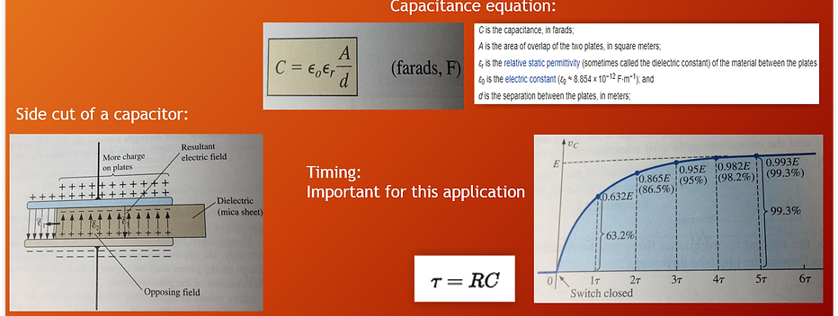

Normally there is an electrode show to the left in orange. This forms a capacitor with the ground planes pictured in gray. When a person comes along and starts to touch the electrode they form a virtual ground and another conductor. They are separated by the dielectric of the soldermask as well as their skin. This coupling affect increases the capacitance of this new capacitor and changes the charging time constant that the microprocessor can recognize.

Pictured above is the timeline of how the project was meant to advance. This is know as a gantt chart. The major milestones of the project are pictured in blue.

The first part of the design was protecting the device. Shown to the left is where 24 volts are coming into the device. This goes through a fuse to handle any excess current that may happen. D2 is a reverse polarity diode. This is in place in case someone accidentally hooks up the device with the wrong polarity. D1 is TVS or transorb. This is meant to take any voltage spikes from poorly regulated power supplies or static and clamp it to safe voltage. Finally U2 is a 3.3V voltage regulator. The capacitors are in there because the voltage regulator needs them to be stable
The microprocessor selected to achieve this task was the MKE15Z256VLH7. This has a robust touch sensing peripheral. Plenty of I/Os for the electrodes, I2C bus, and PWMs


1 hr
Consultation Meeting
1 hr
Consultation Meeting
1 hr
Consultation Meeting

The microprocessor needs to talk to the digital-to-analog convertor. It does this through I/O pins and communicates through an I2C communication protocol. The DAC is only able to export up to 3.3 volts so an amplifier is needed to get the signal up to 10 volts. For this a non-inverting op-amp was used to increase the voltage up to 10 volts.
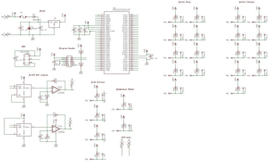
Finally it was all tied together in one big schematic which is pictured above.

The schematic needed to moved to the physical world with a CAD program to create board layouts.
Pictured to the left is where the copper will be for the electrode matrix, buttons, and slider.
The top section will be for all of the analog and digital components.
The board was then manufactured at a PCB board house. A stencil was created to apply solder paste. A pick and place machine places all of the components onto the board and then it is sent through a reflow oven.
What you see to the right is the final product after those processes.


Now that the board is finished we moved onto coding the program for it to function the way we would like it to.
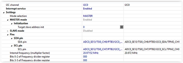
The pictures to the left and above are setting up the I2C communication bus. I2C is a common communication protocol and what was implemented on this project.
Then below is the actual function used to send information to the DACs


The pins for the capacitive touch electrodes were then assigned.
During that assignment another assignment was done to say what kind of control they would be: button, slider, or matrix.
When an electrode senses a touch it creates an interrupt that a service routine needs to deal with.
To the right is the code that says what to do when it senses a touch. It will either effect the intensity (brightness) variable or it will effect the color temperature variable. This was the code that controlled the keypad matrix.


The interrupt function the left is dealing with the predefined push buttons
After that was all tied together we have a working prototype. The video below is a presentation about this project.